Toshiba nC1 Low Voltage Standard Duty Micro Drive
Toshiba Updated: 2007-07-17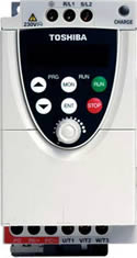
The nC1 Adjustable Speed Drive is a sub-micro, or nano-sized, drive with a full range of features to meet the needs of nearly any user. The nC1 is designed to be a simple drop in replacement for a starter on an existing project or as a new installation. It comes with either single-phase or three-phase input with input voltage as low as 120 V. This makes it an excellent choice for small OEM applications. Side-by-side mounting and the vertical construction of the unit allow for a smaller footprint in your cabinet. The nC1 provides better control of your application, more protection for your motor and more room in your cabinet.
nC1 Standard Specifications
Range 1001P-1007P 2002P-2022P 2001PL-2022PL 2002P-2022P
Input Voltage Rating 120V / Single Phase 230V / Single Phase 230 V / Three Phase 230 V / Single Phase with RFI / EMI Filter
KW Range 0.1 - 0.75KW 0.2 - 2.2KW 0.1 - 2.2KW 0.2 - 2.2 KW
HP Range 1/8 - 1HP 1/4 - 3HP 1/8 - 3HP 1/4 - 3 HP
Overload Rating 150% for 60 seconds
Input Voltage Tolerance +10%, -15% +10%, -15% +10%, -15% +10%, -15%
Input Frequency Rating 50 / 60Hz 50 / 60Hz 50 / 60Hz 50 / 60Hz
Input Frequency Tolerance ±5% ±5% ±5% ±5%
Output Voltage Rating 230V, Three Phase
Color Munsel 5Y8 / 0.5
Control System Sinusoidal PWM Control
Output Voltage Range Adjustable within a range of 100 to 120% of the corrected supply voltage (200V), nonadjustable to any voltage higher than the input voltage
Output Frequency Range 0.5 - 200Hz, Default Setting: 0.5 - 80Hz, Max Frequency: 30 - 200Hz
Minimum Frequency Step 0.1Hz: Operation Panel Setting, 0.2Hz: Analog Input (when the Max Frequency is 100Hz)
Frequency Accuracy Digital Setting: within ±0.5% of the Max Frequency (-10 to +50°C)
Analog Setting: within ±1.0% of the Max Frequency (25°C ± 10°C )
V/f Characteristics V/f, Slip Frequency Compensation, Base Frequency, Base Frequency Voltage and Torque Boost
(adjustable amount)
Frequency Setting Signal Internal Pot on the Front Panel, External Frequency Signal (connectable to a volume with a rated impedance of 3-10 kΩ), VI Terminal (Input Impedance: 42 kΩ (Voltage: 0 - 10Vdc) or 250Ω (Current: 4 - 20 mAdc)). The frequency can be set arbitrarily using a two point setting.
Start-up & Jump Frequency Adjustable within a range of 0.5 - 10Hz, up to 1 frequency can be adjusted together with its widths
PWM Carrier Frequency Selectable from among 2, 4, 8, 12 and 16kHz (Standard Default Setting: 12kHz or 4kHz for models with a Built-In EMI Noise Filter)
Accel / Decel Time Two selectable Accel / Decel Times adjustable from 0.1 to 3000 seconds
Retry Operation Selectable number of retries (maximum 10 times)
If the protection function is activated, the retry function restarts on completion of a check of the main circuit.
Electric Control Charging of Capacitor (Deceleration Time can be shortened by activating Forced Shortened Deceleration mode.)
Dynamic Braking Braking Start Frequency: 0 to Max Frequency, Braking Rate: 0 to 100%, Braking Time: 0 to 20 seconds
Input Terminal Functions Forward / Reverse Run Input Signal, Jog Run Input Signal, Standby Signal, Preset-Speed Operation Input Signal, Reset Input Signal, etc.
Output Terminal Functions Frequency Lower Limit Output Signal, Frequency Upper Limit Output Signal, Low-Speed Detection Output Signal, Specified Speed Attainment Output Signal, etc., Open Collector, RY Output
Failure Detection Signal 1 Form C contact, Rated: 250Vac, 2A, cosΦ = 0.4
FM / AM Output PWM Output: (1mAdc full-scale DC ammeter or 7.5Vdc full-scale DC ammeter / Rectifier-type AC Voltmeter, 225% Current Max 1mAdc, 7.5Vdc full-scale)
Protective Function Stall Prevention, Current Limitation, Overcurrent, Output Short Circuit, Overvoltage, Overvoltage Limitation, Undervoltage, Ground Fault, Power Supply Phase Failure, Output Phase Failure Overload Protection by Electronic Thermal Function, Armature Overload at Start-up, Load-Side Overtorque at Start-up, Overheating Prevention, Detection of Analog Signal Break
Momentary Power Failure Protection Auto-Restart Control after momentary power failure
Electronic Thermal Characteristics Switching between Standard Motor / Constant- Torque VF Motor, Overload Trip, Overload Stall Selection
4-Digit, 7-Segment LED Frequency: Inverter Output Frequency
Alarm: Stall Alarm "C," Overvoltage Alarm "P," Overload Alarm "L," Overheat Alarm "H."
Status: Inverter Status (Frequency, Cause of Activation of Protective Function, Input / Output Voltage, Output Current, etc.) and Parameter Settings
Free-Unit Display: Arbitrary Unit (e.g. Rotating Speed) Corresponding to Output Frequency
Indicator Lamps indicating the inverter status by lighting, such as RUN lamp and PRG lamp
Use Environments Indoor- Altitude: 1000 m (maximum), not exposed to direct sunlight, corrosive gas, explosive gas or vibration (less than 5.9m x 2) (10 to 55 Hz)
Ambient Temperature -10 to +50˚C
Storage Temperature -20 to +65˚C
Relative Humidity 20 to 93% Non-Condensing
nC1 Engineering Specs
nC1 Manual
nC1 Manual Rev 3
NC1 Brochure
PCM001Z Users Manual
PCM001Z V.14
PCS001Z Users Manual
PCS001Z V.1
Related Manuals
Toshiba S11 Low Voltage Standard Duty Micro Drive
Toshiba G3+ Low Voltage Severe Duty Specialty Drive
Toshiba AS1 Low Voltage Standard Duty Integrator Drive
Toshiba Q7 Low Voltage Variable Torque HVAC Drive
Toshiba W7 Low Voltage Variable Torque Water/Wastewater Drive
Toshiba HX7 Low Voltage Standard Duty Specialty Drive
Toshiba T300MVi Medium Voltage Standard Duty All Purpose Drive
Toshiba H7 Low Voltage Standard Duty Industrial Drive
Toshiba G7 Low Voltage Severe Duty Industrial Drive
Toshiba MTX NEMA 3R MV Severe Outdoor Drive
Toshiba G9 Low Voltage Severe Duty Industrial Drive
Hitachi SC-OPE 3H/3I Operator Interface and Networking Devices